
Looking to skip to the good stuff and get started JUMP to the END to download
I was inspired by Ivan Kuleshov and his Raspberry Pi Server Mark III project. So much so that I wanted to design a smart cooling solution to go with it. Finding the right components that would allow for easy updates/upgrades was a challenge doing these troubling times. Choosing between ESP32 with TFT and other solutions was a determining factor when using Home Assistant. Adafruit showed a demo last year of a just a chip ESP32-S2 TFT Feather but didn’t release it until after I started gathering parts for PiVAC. The PiVAC fetches temps approx. every 2 minutes from each Pi thats running docker with Prometheus and uses those values to set fan speeds of up to 3 zones. I’m sure people smarter than I could modify the Python code to get values from anywhere instead.
Starting with the housing was first on the list I wanted to fit the standard Rack Mount 2U form factor. I also didn’t have my hands on my POE splitter yet so usb power it was. Keeping this skinny enough to fit between two other Pi Severs prevented me from closing up the side but maybe down the road someone will design something even better.
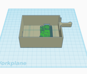
Starting with the housing was first on the list I wanted to fit the standard Rack Mount 2U form factor. I also didn’t have my hands on my POE splitter yet so usb power it was. Keeping this skinny enough to fit between two other Pi Severs prevented me from closing up the side but maybe down the road someone will design something even better.

The initial components consisted of a 40-pin GPIO 1 to 2 Expansion Board and an Adafruit Industries Mini PiTFT Color 135×240. With a little help from some demo code on Learn Adafruit I was able to get the screen’s default orientation rotated and colors figured out. A generic search for Linux command lines got me to the IP Address and CPU Usage.


The initial components consisted of a 40-pin GPIO 1 to 2 Expansion Board and an Adafruit Industries Mini PiTFT Color 135×240. With a little help from some demo code on Learn Adafruit I was able to get the screen’s default orientation rotated and colors figured out. A generic search for Linux command lines got me to the IP Address and CPU Usage.


Seeing as I went with Noctua 5v 80x80x25 mm fans they come with extension cables. Using fine tweezer you can pop out and reverse the signal/RPM(BLUE) and tachometer/RPM(GREEN) pins on the extensions ***ONLY*** as seen below. This is necessary for the Adafruit 16-Channel PWM board since the pinout falls ground-power-signal.


Seeing as I went with Noctua 5v 80x80x25 mm fans they come with extension cables. Using fine tweezer you can pop out and reverse the signal/RPM(BLUE) and tachometer/RPM(GREEN) pins on the extensions ***ONLY*** as seen below. This is necessary for the Adafruit 16-Channel PWM board since the pinout falls ground-power-signal.


It was very important to me that this project be fully powered from my Ubiquiti USW-PRO-24-POE switch to that power cycling could be done remotely and it declutters my rack. With that said it would not have been possible without finding the WaveShare PoE Ethernet/USB HUB HAT for Raspberry Pi. Without this two part board I would of had to tear apart a POE splitter to attempt to get to fit inside the enclosure. Seeing as I don’t have a need for the usb ports or ethernet chip I decided to leave off the top sister board as the data pins interfere with the zero WIFI. A quick solder up of 2pin JST and fan headers on the Adafruit 16-Channel PWM / Servo Bonnet with 3d printed fan headers made for a nice compact form factor. The two power pins from the WaveShare made it easy to attached to a Micro USB Male and 2pin JST that I clipped off a 3d printer fan.
SIDE NOTE
The power holes on the server bonnet are **NOT** standard spacing some modification will be needed to the pins.


A few manual modifications to the enclosure ensured for a secure fit of the waveshare board since plugging in the POE might shift things around. All in all I will be redesigning the enclosure to include mounting holes for both the waveshare and pi zero so hardware can be easily used on both. If I get enough(100) re-tweets on the twitter post I’ll post the STL files for the Alpha and Beta enclosure.


A few manual modifications to the enclosure ensured for a secure fit of the waveshare board since plugging in the POE might shift things around. All in all I will be redesigning the enclosure to include mounting holes for both the waveshare and pi zero so hardware can be easily used on both. If I get enough(100) re-tweets on the twitter post I’ll post the STL files for the Alpha and Beta enclosure.


